sabato 12 giugno 2021

ANN leg tilting classification, finally this seems to work :)

                                         https://www.youtube.com/watch?v=rep5edOnzvU

How it works: a Spring Boot PI4J and Weka based java application running on a Raspberry PI3 allows reading the 12 accelerometers on the legs junctions, plus the 4 buttons on the feet. An additional accelerometer on the head of the spider provides unique head 3 axis acceleration. The artificial neural networks, read all of the sensors values and upon a trained model "classify" data to provide a feedback on which one is the tilted leg. Upon this, the system can decide how to try to rebalance, then perform another classification and try to rebalance, until the spider is "flattened" horizontally. 


Next step will be to implement the read-classify-balance process mentioned above and interface the LIDAR set under the spider.


The classifier used that is a multi layer perceptron:


arff format used:

% 1. Title: Tss balance condition
% 2. Sources:
%      (a) tss arff generation routine
%

@RELATION tssbalance

@ATTRIBUTE LEG_SEG_ACC_A_0_X NUMERIC
@ATTRIBUTE LEG_SEG_ACC_A_0_Y NUMERIC
@ATTRIBUTE LEG_SEG_ACC_A_1_X NUMERIC
@ATTRIBUTE LEG_SEG_ACC_A_1_Y NUMERIC
@ATTRIBUTE LEG_SEG_ACC_A_2_X NUMERIC
@ATTRIBUTE LEG_SEG_ACC_A_2_Y NUMERIC
@ATTRIBUTE LEG_SEG_ACC_B_9_X NUMERIC
@ATTRIBUTE LEG_SEG_ACC_B_9_Y NUMERIC
@ATTRIBUTE LEG_SEG_ACC_B_10_X NUMERIC
@ATTRIBUTE LEG_SEG_ACC_B_10_Y NUMERIC
@ATTRIBUTE LEG_SEG_ACC_B_11_X NUMERIC
@ATTRIBUTE LEG_SEG_ACC_B_11_Y NUMERIC
@ATTRIBUTE LEG_SEG_ACC_C_6_X NUMERIC
@ATTRIBUTE LEG_SEG_ACC_C_6_Y NUMERIC
@ATTRIBUTE LEG_SEG_ACC_C_7_X NUMERIC
@ATTRIBUTE LEG_SEG_ACC_C_7_Y NUMERIC
@ATTRIBUTE LEG_SEG_ACC_C_8_X NUMERIC
@ATTRIBUTE LEG_SEG_ACC_C_8_Y NUMERIC
@ATTRIBUTE LEG_SEG_ACC_D_3_X NUMERIC
@ATTRIBUTE LEG_SEG_ACC_D_3_Y NUMERIC
@ATTRIBUTE LEG_SEG_ACC_D_4_X NUMERIC
@ATTRIBUTE LEG_SEG_ACC_D_4_Y NUMERIC
@ATTRIBUTE LEG_SEG_ACC_D_5_X NUMERIC
@ATTRIBUTE LEG_SEG_ACC_D_5_Y NUMERIC
@ATTRIBUTE FOOT_A0 {0, 1}
@ATTRIBUTE FOOT_B9 {0, 1}
@ATTRIBUTE FOOT_C6 {0, 1}
@ATTRIBUTE FOOT_D3 {0, 1}
@ATTRIBUTE HEAD_ACC_X NUMERIC
@ATTRIBUTE HEAD_ACC_Y NUMERIC
@ATTRIBUTE HEAD_ACC_Z NUMERIC
@ATTRIBUTE CLASS {LEG_A,LEG_B,LEG_C, LEG_D, NONE}

@DATA
To populate this data section some leg-named REST endpoints have been implemented that tilt a specific leg and save a leg tilted specific arff file. The merge of all these 5 files (LEG_ALEG_B, LEG_C, LEG_D, NONE) makes the training alle-legs arff file used to train the model.

giovedì 4 febbraio 2021

Lidar data parsing

Sample of Lidar A1M8 from Slamtec, for a scan data packet


mercoledì 6 gennaio 2021

Tss training dataset for Weka ann, single files, one for each tilted leg (A,B,C,D) and one for no leg tilted (NONE):

tss_training_dataset_LEG_A_1609957235461.arff

tss_training_dataset_LEG_B_1609957257019.arff

tss_training_dataset_LEG_C_1609957278586.arff

tss_training_dataset_LEG_D_1609957300163.arff

tss_training_dataset_NONE_1609957213880.arff


and merged arff file:


tss_training_dataset_LEGS.arff


REST endpoint to generate all ARFF for the ann:

http://raspberry:8080/resources/ann/arff/all


All files are available on git repo.


Connecting the Slamtech A1M8 RPLIDAR to the Raspberry, Raspbian

dmesg


lsusb


Lidar is rotating and no power consumption issue detected on dmesg so far.


domenica 3 gennaio 2021

 Checking USB devices:


USB devices they should show up with lsusb and/or usb-devices when (physically) connected to the Pi. With nothing connected to the USB ports, you get as output:


domenica 6 dicembre 2020

 Mechanics completed, via REST endpoints the pi4j Spring Boot implementation executes simple commands, like stand up and tilt on each leg.


Current consumption calculation for PI GPIO:

10mA Raspberry PI servo hat

12 x 350µA for adxl 335 accelerometers 8400 µA 0 4,2 milli Ampere


The operating voltage of the GPIO pins is 3.3v with a maximum current draw of 16mA


venerdì 15 maggio 2020

mercoledì 13 maggio 2020

Software installation

Java:
sudo apt-get install openjdk-8-jre-headless -y


WiringPi:
http://wiringpi.com/

sudo apt-get install wiringpi

Pi4J:

https://pi4j.com/1.2/install.html

curl -sSL https://pi4j.com/install | sudo bash


Tss:
https://gitlab.com/stefano.falconetti/tss

sabato 2 maggio 2020

Mapping between PCA9685 PWM i2c controller and leg segments:


PWM I2C controller pin number
Leg segment
00
A0
01
A1
02
A2
03
D3
04
D4
05
D5
06
C6
07
C8
08
C7
09
B9
10
B11
11
B10


Power voltage: 5v
Power current all legs and segments active:

domenica 15 dicembre 2019

The analog accelerometer


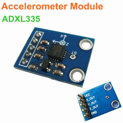
These will be 12, of type ADXL 335 - 3 axis analog output accelerometer:

ADXL335-3-axis-Analog-Output-Accelerometer-Module-angular-transducer-for-Arduino


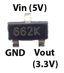
Power consumption is 1.5 mA and it has 3.3 regulator allowing 3 - 5 v powering.


Risultati immagini per .662k smd

I will put one of these analog accelerometer on each servo motor with the 3M dual lock, that is strong and allow removal and replacement.


giovedì 12 dicembre 2019

Review of the i2c Addresses with the new hardware


New i2c scan is as follow now, after changing the hardware.

AB Electronics ADC PI
Adafruit PWM Hat

pi@raspberrypi:~ $ sudo i2cdetect -y 1
     0  1  2  3  4  5  6  7  8  9  a  b  c  d  e  f
00:          -- -- -- -- -- -- -- -- -- -- -- -- --
10: -- -- -- -- -- -- -- -- -- -- -- -- -- -- -- --
20: -- -- -- -- -- -- -- -- -- -- -- -- -- -- -- --
30: -- -- -- -- -- -- -- -- -- -- -- -- -- -- -- --
40: 40 -- -- -- -- -- -- -- -- -- -- -- -- -- -- --
50: -- -- -- -- -- -- -- -- -- -- -- -- -- -- -- --
60: -- -- -- -- -- -- -- -- 68 69 6a 6b 6c 6d -- --
70: 70 -- -- -- -- -- -- -- 

Where each address is taken as per the below table:

40: Adafruit 16 Channels PWM Hat

68: AB Electr ADC PI board 1 chip 1

69: AB Electr ADC PI board 1 chip 2

6a: AB Electr ADC PI board 2 chip 1

6b: AB Electr ADC PI board 2 chip 2

6c: AB Electr ADC PI board 3 chip 1

6d: AB Electr ADC PI board 3 chip 2

70: Adafruit 16 Channels PWM Hat.. this must be a second address used by Adafruit 16 Channels PWM Hat


sabato 30 novembre 2019

IO PI Plus issue

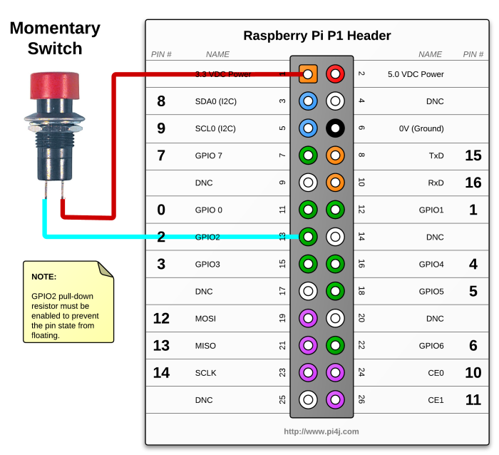
After few tests it seems the board is not announcing itself anymore on the i2c bus. The plans, given that so many inputs are not needed on the digital side, is to use for GIO pins:

domenica 24 novembre 2019

giovedì 21 novembre 2019

Well, I need 24 ADC connected to I2C bus, for 12 ADXL335, threee axis analog accelerometer, to read at least 2 axis output from each of them.


Because each segment of the leg needs two axis accelerometer, it means there is the need for:

12 servo motors

each servo needs two axis to get the position (rotation)

so: 12 leg segmenst  * 2 channels each accelerometer = 24 analog input ADC is required.

A good option is this stackable ADC, with 8 channels each board:


ADC Pi Zero


https://www.abelectronics.co.uk/p/69/adc-pi-raspberry-pi-analogue-to-digital-converter


Each of these has 2 ADC chips of type MCP3424 

That seems to be supported by Pi4j:

https://github.com/Pi4J/pi4j/blob/master/pi4j-example/src/main/java/MCP23017GpioExample.java Up to 4:

can be connected using these I2C addresses:

0x68
0x69

0x6A
0x6B

0x6C
0x6D

0x6E

0x6F

Each board will take two addresses as each board has two chip. Way to setup the I2C address is this:


Board features (copied from the AB electronics page):

8 x 17-bit 0 to 5V Single Ended Inputs
Control via the Raspberry Pi I2C port
Stack up to 4 ADC Pi boards on a single Raspberry Pi
Jumper selectable I2C addresses
Buffered 5V I2C port
Based on the MCP3424 from Microchip Technologies Inc
Single Ended full-scale range of 5.0V
On-board 2.048V reference voltage (Accuracy  ± 0.05%, Drift: 15 ppm/°C)
On-Board Programmable Gain Amplifier (PGA): Gains of 1, 2, 4 or 8
Programmable Data Rate Options:
   - 3.75 SPS (17 bits)
   - 15 SPS (15 bits)
   - 60 SPS (13 bits)
   - 240 SPS (11 bits)
One-Shot or Continuous Conversion Options
The ADC Pi is an 8 channel 17 bit analogue to digital converter designed to work with the Raspberry Pi. The ADC Pi is based on two Microchip MCP3424 A/D converters each containing 4 analogue inputs.  The MCP3424 is a delta-sigma A/D converter with low noise differential inputs.

We designed the ADC Pi to work as a single ended A/D converter using the internal 2.048V reference voltage with the -V pins tied to ground. A voltage divider on the ADC Pi board brings the input voltage range to a much more useful 0 – 5.06V. In this configuration the sample size is 17 bits for each channel.

The ADC Pi is powered through the host Raspberry Pi using the GPIO port and extended pins on the GPIO connector allow you to stack the ADC Pi along with other expansion boards.

The two MCP3424 A/D converters communicate via i2c to the host Raspberry Pi giving you eight analogue inputs to use.  A logic level converter is included on the ADC Pi board giving you a buffered 5V i2c port making it easy to add other I2C devices which operate at 5 volts without damaging the raspberry pi 3.3 volt i2c port.  The i2c buffer uses N-channel mosfets with a maximum drain current of 100mA.

The I2C address bits are selectable using the on-board jumpers.  The MCP3424 supports up to 8 different I2C addresses so with two A/D converters on each ADC Pi you can stack up to 4 ADC Pi boards on a single Raspberry Pi giving you 32 ADC inputs.

The MCP3424 contains a programmable Gain Amplifier giving the user a selectable gain of x1, x2, x4 or x8 before the analogue to digital conversion takes place.

The data rate for analogue to digital conversions is 3.75 (17 bit), 15 (15 bit), 60 (13 bit) or 240 (11 bit) samples per second. Data rate and resolution can be configured within software using the I2C interface.

We have a knowledge base article, ADC Sample Rate Comparison which has more detailed sample information and test scripts to compare the different MCP2424 ADC chip bit and sample rates.

Unused inputs should be tied to ground.

To connect the ADC to the ADXL335, I'm using the explanation as shown in the below link:


The circuit will require no extra components because I will use the ADC PI instead of the differential one:


Connect the VCC pin on the ADXL335 board to 3.3V on the GPIO header.
Connect the GND on the ADXL335  to GND on the GPIO header.
Now we need to connect the output from the ADXL335 board to the ADC inputs, as the output from the ADXL335 is up to 3.3 volts we need to add a voltage divider between the ADXL335  output and the ADC Pi positive inputs on each channel. ADC Pi comes with a voltage divide on board, so no need for an extra external one.
Connect the X pin on the ADXL335  to input 1 on the ADC Pi
Connect the Y pin on the ADXL335  to input 2 on the ADC Pi 
The Z pin will not be connected, to measure rotation 2 axis will be enough.

lunedì 18 novembre 2019

First tests with the software: display and servos


Spring Boot application with PI4J library

REST for display control


REST for stepper motor control via PVM


Motor zero test


mercoledì 13 novembre 2019

Devices: Oled Display

The small display on the board is a tiny and cheap display, whose specs follow:

Feature:

Resolution: 128*64
Control chip: SSH1106
Display area: 29.42 x 14.7mm
Driving voltage: 3.3-5V
Operating temperature: -40 ℃ to 70 ℃
Interface type: IIC/I2C  interface

Pin definitions:

1> GND (power ground)
2> VCC (positive power supply)
3> SCL (clock line)
4> SDA (data line)

About control chip SSH1106:

SSG1106 compatible with SSD1306 basic, difference is that SSH1106 control chip RAM space is 132*64, while SSD1306 space is 128*64.
The 1.3-inch OLED 128*64 dot matrix, so in the middle of the screen production took 128 row. When using SSD1306 program point SSH1106 screen, only need to change address to 0x02 row to start.

martedì 12 novembre 2019

Force sensor ddidn't work ! Bending them means breaking the contacts.


And because of this I had to switch to another approach, less expensive (I already lost 7 * 4 euros :( ) and with no noise or ADC conversions to do. Because of these, i went with a button on top of a sticky cable fix, and created 4 contact sensors. Quite raw and simple, but cheaper and hopefully working better.


domenica 3 novembre 2019

Legs forrce sensing sensors mount

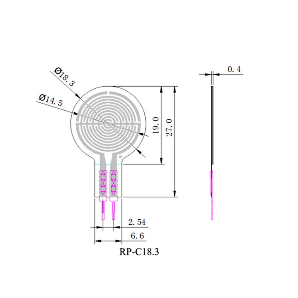
Sensor type is:

GS04741


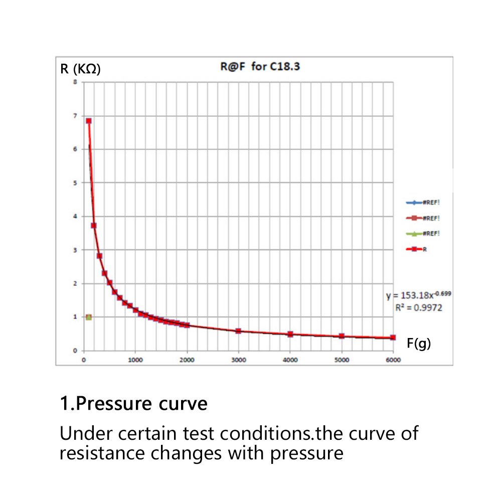
This sensor has this resistance/force response curve:


and this measures:

About the sensor


Features:
  • The flexible sensor has the characteristics of flexible ultra-thin, ultra-low power consumption and extreme speed response, etc.
  • Small size, this flexible pressure sensor is based on new nanometer pressure-sensitive materials supplemented by ultra-thin film substrate.
  • This pressure sensor has the characteristic of high stability, high consistency.
  • Highly sensitive flexible nanometer materials can realize highly sensitive detection of pressure.
  • When sensor detects outside pressure, the resistance of sensor will change.
  • Pressure signal can be converted into a corresponding electrical signal output using simple circuit.

Specifications:
Model: RP-C18.3-STManufacturing process: thin film
Output signal: analog
Pressure induction range: 20g-6kg
Trigger: 20 g, triggered, default Resistance <200 kΩThickness: 0.4mm
Not trigger resistance: > 10MΩ
Activation time: <0.01s
Delay: +10%, (RF+-RF-)/FR+,1000g force
Response time: < 10ms
Size: 3.2 x 1.8cm / 1.25 x 0.7in

Weight: 5g

Pull down resistor, needed to solve floating logical levels issues:


force___flex_fsrpulldownsch.gif

force___flex_fsrpulldowndia.png


Assembled "feets" are like below :)