Current consumption calculation for PI GPIO:
10mA Raspberry PI servo hat
12 x 350µA for adxl 335 accelerometers 8400 µA 0 4,2 milli Ampere
The operating voltage of the GPIO pins is 3.3v with a maximum current draw of 16mA
domenica 6 dicembre 2020

venerdì 15 maggio 2020


mercoledì 13 maggio 2020
Software installation
Java:
sudo apt-get install openjdk-8-jre-headless -y
WiringPi:
http://wiringpi.com/
Pi4J:
https://pi4j.com/1.2/install.html
curl -sSL https://pi4j.com/install | sudo bash
Tss:
https://gitlab.com/stefano.falconetti/tss
sudo apt-get install openjdk-8-jre-headless -y
WiringPi:
http://wiringpi.com/
sudo apt-get install wiringpi
Pi4J:
https://pi4j.com/1.2/install.html
curl -sSL https://pi4j.com/install | sudo bash
Tss:
https://gitlab.com/stefano.falconetti/tss
martedì 12 maggio 2020
PWM Servo hat and short circuit between servo power and GPIO:
https://forums.adafruit.com/viewtopic.php?f=8&t=165285&p=811358#p811358


https://forums.adafruit.com/viewtopic.php?f=8&t=165285&p=811358#p811358


sabato 2 maggio 2020
domenica 15 dicembre 2019
The analog accelerometer
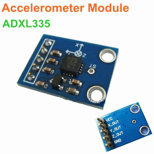
These will be 12, of type ADXL 335 - 3 axis analog output accelerometer:

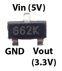
Power consumption is 1.5 mA and it has 3.3 regulator allowing 3 - 5 v powering.

I will put one of these analog accelerometer on each servo motor with the 3M dual lock, that is strong and allow removal and replacement.
giovedì 12 dicembre 2019
Review of the i2c Addresses with the new hardware
New i2c scan is as follow now, after changing the hardware.
AB Electronics ADC PI
Adafruit PWM Hat
pi@raspberrypi:~ $ sudo i2cdetect -y 1
0 1 2 3 4 5 6 7 8 9 a b c d e f
00: -- -- -- -- -- -- -- -- -- -- -- -- --
10: -- -- -- -- -- -- -- -- -- -- -- -- -- -- -- --
20: -- -- -- -- -- -- -- -- -- -- -- -- -- -- -- --
30: -- -- -- -- -- -- -- -- -- -- -- -- -- -- -- --
40: 40 -- -- -- -- -- -- -- -- -- -- -- -- -- -- --
50: -- -- -- -- -- -- -- -- -- -- -- -- -- -- -- --
60: -- -- -- -- -- -- -- -- 68 69 6a 6b 6c 6d -- --
70: 70 -- -- -- -- -- -- --
Where each address is taken as per the below table:
40: Adafruit 16 Channels PWM Hat
68: AB Electr ADC PI board 1 chip 1
69: AB Electr ADC PI board 1 chip 2
6a: AB Electr ADC PI board 2 chip 1
6b: AB Electr ADC PI board 2 chip 2
6c: AB Electr ADC PI board 3 chip 1
6d: AB Electr ADC PI board 3 chip 2
70: Adafruit 16 Channels PWM Hat.. this must be a second address used by Adafruit 16 Channels PWM Hat


Iscriviti a:
Post (Atom)